
těleso škrtící klapky V6 - foto

těleso škrtící klapky V6 - foto
zdravím, zas vymejšlím nesmysly a tak bych poprosil majitele nějaký starší alfy s V6 motorem, kde je škrtící klapka ovládaná lankem, aby mi oměřil rozteč upevňovacích šroubů a taky třeba klapku nafotil - zejména pokud má potenciometr tak jak ten potenciometr vypadá a pokud by to ještě šlo, tak by mě zajímal i průměr té klapky (tuším že je něco kolem 70mm ale nejsem si jist..)
AR 159 SW TBI TI
AR 156 V6 SW
AR Giulietta 1.4 MA
Fiat Coupe 2.0 16v
Fiat Tipo 2096ccm 16v
ex: bravo HGT, 147 1.6, Stilo 2.0 16v
AR 156 V6 SW
AR Giulietta 1.4 MA
Fiat Coupe 2.0 16v
Fiat Tipo 2096ccm 16v
ex: bravo HGT, 147 1.6, Stilo 2.0 16v
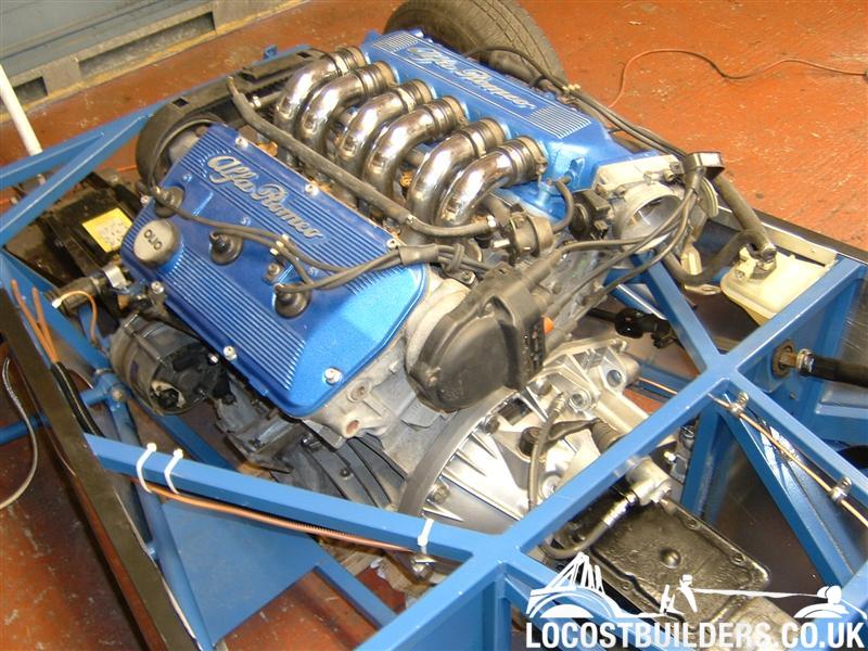
po chvíli googlování jsme našel foto - to důležitý pro mě je vidět, krom rozteče (snad je stejná na všech V6- oměřím na 156tce v garáži..) a průměru...
ps.: nemá někdo škrtící klapku ovládanou lankem předběžně k prodeji?
AR 159 SW TBI TI
AR 156 V6 SW
AR Giulietta 1.4 MA
Fiat Coupe 2.0 16v
Fiat Tipo 2096ccm 16v
ex: bravo HGT, 147 1.6, Stilo 2.0 16v
AR 156 V6 SW
AR Giulietta 1.4 MA
Fiat Coupe 2.0 16v
Fiat Tipo 2096ccm 16v
ex: bravo HGT, 147 1.6, Stilo 2.0 16v
- Milano75
- SemTuFurt
- Příspěvky: 5150
- Registrován: 7.5.2008, stř 15:22
- Bydliště: Jihlava
- Kontaktovat uživatele:
Re: těleso škrtící klapky V6 - foto
se ti na to mrknu....
Alfa Romeo 75 3.0 V6 QV America
Alfa Romeo 75 2,0TS
Alfa Romeo Alfetta GT 1,8 1975 + skelet 1981
Alfa Romoe 159 2,4JTDM SW TI
Alfa Romeo 75 2,0TS
Alfa Romeo Alfetta GT 1,8 1975 + skelet 1981
Alfa Romoe 159 2,4JTDM SW TI
Re: těleso škrtící klapky V6 - foto
nemusíš..už mám dostatečnou fotodokomentaci i s rozměrama.. nakonec mi ta klapka stejně bude k ničemu ať už z prostorovýho hlediska, nebo z toho že by na mým motoru správně neplnila účel..
AR 159 SW TBI TI
AR 156 V6 SW
AR Giulietta 1.4 MA
Fiat Coupe 2.0 16v
Fiat Tipo 2096ccm 16v
ex: bravo HGT, 147 1.6, Stilo 2.0 16v
AR 156 V6 SW
AR Giulietta 1.4 MA
Fiat Coupe 2.0 16v
Fiat Tipo 2096ccm 16v
ex: bravo HGT, 147 1.6, Stilo 2.0 16v
- Milano75
- SemTuFurt
- Příspěvky: 5150
- Registrován: 7.5.2008, stř 15:22
- Bydliště: Jihlava
- Kontaktovat uživatele:
Re: těleso škrtící klapky V6 - foto
hojte
nahrazoval už někdo starý typ váhy vzduchu za nový??
konkrétně na V6 motronicu??
nahrazoval už někdo starý typ váhy vzduchu za nový??
konkrétně na V6 motronicu??
Alfa Romeo 75 3.0 V6 QV America
Alfa Romeo 75 2,0TS
Alfa Romeo Alfetta GT 1,8 1975 + skelet 1981
Alfa Romoe 159 2,4JTDM SW TI
Alfa Romeo 75 2,0TS
Alfa Romeo Alfetta GT 1,8 1975 + skelet 1981
Alfa Romoe 159 2,4JTDM SW TI
- Hampice
- SemTuFurt
- Příspěvky: 8674
- Registrován: 7.11.2009, sob 05:48
- Bydliště: Jesenice (Praha-západ)

Re: těleso škrtící klapky V6 - foto
Nechci to tvrdit, ale myslím, že to nepůjde. Budou uplně jiný hodnoty i napájení. Stará váhá má navíc v sobě i teploměr nasávaného vzduchu (u nové nevím).
Btw, kdybys potřeboval, můžu jednu tu starou postrádat
Btw, kdybys potřeboval, můžu jednu tu starou postrádat
Alfa Romeo 164 QV (1992)
Alfa Romeo Giulia 2.0T Super (2018)
Alfa Romeo Giulia 2.0T Super (2018)
- Ladin 164V6
- SemTuFurt
- Příspěvky: 5892
- Registrován: 15.1.2008, úte 15:52
- Bydliště: Karlovy Vary
Re: těleso škrtící klapky V6 - foto
Kdysi mi nekdo rikal, ze na BMW si ty klapkovy vahy lidi menili za MAF, ale detaily nevim.
164 Q4 se v motoru poznaji prave podle tohohle MAF, ale maji i o generaci novejsi Motronic...
164 Q4 se v motoru poznaji prave podle tohohle MAF, ale maji i o generaci novejsi Motronic...
AR 164 3.0 24V Super 171kW Nero601 92' (Zombie - la machina arrogante)
Bmw 3er M3 3.2 Convertible Alpinweiss3 98'
Bmw 3er M3d2 SportWagon TitanSilber '06
Renault Kangoo 1.2 16V '08 :D
Vždycky všechno OFF...
Bmw 3er M3 3.2 Convertible Alpinweiss3 98'
Bmw 3er M3d2 SportWagon TitanSilber '06
Renault Kangoo 1.2 16V '08 :D
Vždycky všechno OFF...
- Hampice
- SemTuFurt
- Příspěvky: 8674
- Registrován: 7.11.2009, sob 05:48
- Bydliště: Jesenice (Praha-západ)
Re: těleso škrtící klapky V6 - foto
Právě... U 24V - Motronic M1.7 - by to možná šlo, ale 75 má ještě ML4.1...
Alfa Romeo 164 QV (1992)
Alfa Romeo Giulia 2.0T Super (2018)
Alfa Romeo Giulia 2.0T Super (2018)
Re: těleso škrtící klapky V6 - foto
zase trochu omýt poťák isopropylem a je ta stará skoro nesmrtelná.
JInak většinou je KO ten obtokovej selenoid pro neutrál, než váha jako taková..tam pomalu není co zničit..
JInak většinou je KO ten obtokovej selenoid pro neutrál, než váha jako taková..tam pomalu není co zničit..
- Milano75
- SemTuFurt
- Příspěvky: 5150
- Registrován: 7.5.2008, stř 15:22
- Bydliště: Jihlava
- Kontaktovat uživatele:
Re: těleso škrtící klapky V6 - foto
jen tak právě laboruju:) td už me začíná lézt krkem, jak mě havarovalo turbo z A6ky a motor sem musel chcípnout rozpálený, tak to samozřejmě odsralo těsnění pod hlavou  , takže sem začal pokukovat po atmo motoru, který má hlavně 200 HP v serii a jsou dostupnější než VMmotori
V6 motoru se nechce do otáček, jako by se dusí, když se ohřeje je to už lepší, ale není to pořád ono, je cítit hodně benzín, kouříto a nemám zapojenou jedny svody do výfuku, což by snad nemělo tolik vadit
sem to chtěl natočit na mobil, ale naposledy, když sem dal baterku a začal startovat, tak se zakouřilo od startéru (ani se neootočil)
dále po vypnutí klíčku i nadále svítily kontrolky, otáčkoměr byl na max. a jedno relé v mot. prostoru chrčelo, dokud sem ho neodpojil
dál mě ještě štve, že pal. pumpa se rozeběhne až při startování né při oročení klíčkem do polohy 1
kabely by měli být ok, svíčky jsem ještě nestihl vyměnit a lambda je nová
na vyčištění té váhy sem se zrovna o výkendu chystal, věci sem si už na to sehnal
TO Hampi: povyměnuji a pročistím co se dá a pokud by to bylo možné, tak bych byl rád, kdyby jsi mi tu svou pujčil na vyzkoušení
jinak ten nápad s váhou vzduchu je od je od týpka co to dával do GTV6 na jetronic, někde to mám černé na bílém, hodím to pak sem
EDIT:
zde je origo i s obrázky :
http://alfagtv6.com/msdocs/3L_update_Conversion.doc
3.0L Conversion 1985 GTV6 – by David Schmidt – Nov 2004
I’ve put this document together to detail the processes I went through to:
1. Install a 164 3.0L motor into my 1985 GTV6
2. Build & Install larger intake runners
3. Remove the AFM, stock Air Intake tube and Air Box
4. Upgrade the Alternator
5. Install the Megasquirt EMS
The information may be useful to others wanting to tackle a 3.0L 12V conversion on an Alfa GTV6 at a reasonable cost. It is by no means the recommended method to do the conversions and there may be other, probably easier ways, to achieve the end result. The GTV6.org website proved invaluable in the process but quite a deal of time is required to locate all the required information. Some ideas are my own and some are borrowed, so any comments/suggestions are most welcome. Hopefully this will provide a basis for others to add their solutions to the conversion issues encountered and be a useful one stop reference for others. The document could easily be altered for a 3.0L 24V conversion, 3.0L 12V 75 conversion, etc, and you are welcome to use any part of it, photos included
Normal home workshop tools were used or “special” tools manufactured to get the job done. When talking LH & RH I’m looking at the engine from a driver perspective in a RWD GTV6.
I purchased a 3.0L 12V motor from an accident damaged automatic Alfa164 minus the Plenum, Distributor and ECU. The motor had only recently been reconditioned so I decided just to carry out the conversion without any modification to the internals. Fortunately I had a spare 2.5L motor as a source for the various other bits and pieces needed for the conversion.
A good engine stand I think is essential in the conversion process and I bolted it up to four of the bell housing mounting holes. Of course it had to be removed from the stand to install the flywheel.
*****************************
MOTOR CONVERSION
Removed the following from the 3.0L
• Timing belt covers.
• Timing Belt
• Belt de-Tensioner (A new kit was installed in the timing belt de-tensioner while it was off the motor)
• RH Cam Pulley – To remove the FWD upper engine mount.
• Water pump
• Flywheel
• Front crank pulley & sensor
• Sump, oil pump and pickup
• Oil level indicator sensor.
• Oil Pump Drive/Distributor plate.
• Front seal cover (to remove the oil pump hex bolts)
• Fuel rail & Injectors
• Inlet runners
• Heater hose adapter from the rear of the LH Cylinder head.
• RH engine mount studs
Bits required from the 2.5L
• Sump
• Oil Pump & Pickup
• Flywheel
• Front pulley
• Water pump
• Cam belt covers
• AAV
• Nuts and Bolts
• Plenum & throttle body
• Distributor & plug leads
• RH engine mount studs
• AC Compressor and mounting bracket
• Injectors and fuel rail if you’re not going to use the 3.0L items
Extra Bits required
• Flywheel spacer
• Longer flywheel bolts if you don’t have them
• Plate for 164 Distributor hole.
• Manifold studs/bolts to suit
• Heater hose adapter.
• Inlet runners
• Inlet pipe & fittings
• K&N Filter
• O2 Sensor and Bung (If you install MS)
• Silicone hoses – although not necessary if your hoses are in good condition.
• 6 & 8mm hex plugs
• Miscellaneous metric nuts and bolts
• Various wires, plugs & sockets for the MS install
With the 3.0L coming from a FWD there were a few mods required to allow the fit into the GTV6.
The studs for the FWD top engine mount were removed and replaced with hex plugs as one hole goes through to the tappet area. One of the holes is required to mount the 2.5L cam belt cover. The problem being the bolt removed is 8mm and the bolt holding the cam belt cover is 6mm. By carefully drilling out the threaded end of a 8mm bolt, a 6mm thread can be tapped inside. Cut a slot across the newly made threaded sleeve and cut off the thread to the require length and screw in into the 8mm hole. The standard 6mm cam belt cover bolt will then screw straight in.
All the spare studs were removed from the LH & RH side of the engine.
I think these were the original alternator and power steering pump mounts. Hex plugs were installed in these holes as well although probably not essential. Some or these were tough to remove but with high tensile locknuts and vice grips, all eventually came out. The longer engine mount studs on the RH side were replaced with the shorter studs from the 2.5L.
****************
FLYWHEEL
I decided to stay with the 2.5 flywheel as this seemed the most straight forward approach for my first install.
The 3.0L being an automatic had the advantage in that the flywheel bolts are about 4mm longer than the 2.5. (I’m not sure about other 3.0L engines). The bolts are ideally suited to the 4mm spacer required to align the starter ring gear.
Many thanks to Daniel for the quality of the spacer.
***********************
SUMP AND OIL PUMP
My first task was to remove the sump, oil pump and pickup and replace it with the 2.5L parts. Keep plenty of paper/rags/etc on the floor under the motor as oil seems to run out continually as the motor is rotated on the engine stand.
The oil pump must be changed as the 164 oil pump drive shaft has a nut and washer to hold the cam shaft driving gear in place. In the 2.5 this gear is held in place by the distributor.
The oil pump and pickup fitted without a problem although the front crankshaft seal cover has to be removed to get the oil pump hex studs out.
The sump did require re-alignment of the two centre rear pan bolts about 4mm toward the front of the motor. This was achieved using a small round file. There’s plenty of bolt surround on the sump pan to do this without weakening the bolt area. Using a combination of 7mm bolts & nuts from both the 2.5 & 3.0, suitable length bolts/studs can be used to bolt up the sump. I did have to remove some metal on the block just below the engine mounts as there is not enough room to install a bolt of the correct length to the sump pan in this spot. A stud in lieu of the through-bolt may solve this but I wasn’t going to remove the sump just to get these bolts in.
I found out after bolting up the sump pan that the rear edge needed machining back a little. I used a burring tool and a belt sander to achieve this. I would be much easier to do this before fitting the sump. I should have done a bit more reading on the GTV6 site as this was covered in one discussion.
****************
OIL DIP STICK
I checked the position of the both the 2.5 and 3.0 dip sticks before the bottom sump plate was bolted up and found they were within a mm of each other so decided to leave the 3.0L dip stick as its much easier to get to than the original 2.5L.
*********************
164 DISTRIBUTOR HOLE
You need to make up a cover plate for the 164 distributor hole if you’re using the 2.5 distributor.
*********************
OIL LEVEL SENSOR
The hole was plugged with a brass adapter, silver soldered shut. The later 2.5 engines have a plug screwed in this hole so that can be used instead. My donor 2.5 did not have this hole drilled and threaded in the engine block.
*********************
REAR HEATER HOSE ADAPTER
The 3.0L heater hose adapter is a larger diameter than the 2.5L. This was replaced with a brass adapter and nut & tail to suit the 2.5L hose size. The original steel adapter was a real problem to remove. Eventually I filed through the top section to the thread and bent it inwards to remove it.
********************
STARTER MOTOR
The starter motor bolted up and lined up nicely except for the front mount. 4mm out again. Fortunately there are 2 spacers between the front mount and the starter motor brush cover. Undo the nuts and replace the cupped washers with flat washers and it bolts up perfectly.
The starter motor heat shield I had previously modified for the extractors bolted on without problem.
********************
AIR CONDITIONING COMPRESSOR
The 2.5 AC compressor and mounting bracket will bolt straight up to the 3.0L block. The only problem is the AC upper mount hole is not bored & threaded so you need to fit the compressor to the bottom mount and carefully mark the hole. Drill to the required depth and tap an appropriate thread. I actually installed a stainless steel thread restorer in this hole mainly because I did not have the correct tap but had a repair kit to suit that sized metric bolt. The added benefit here is the thread is a lot stronger with the steel thread insert.
I do intend to replace the old York compressor with a rotary type. The bracket and mount from the Alfa 90 with a rotary compressor will fit, so that’s on my “to do” list.
***********************
ALTERNATOR
While the engine was on the engine stand, I decided to fit a higher output alternator. I purchased an 80amp Bosch alternator (from a Mercedes I believe, not sure what year or model). This unit lined up perfectly with the only minimal modification required to the bottom and top mounts. The bottom spacer on the engine mount block needed to be shortened to accommodate the wider alternator bottom mount and some minor modification to the top alternator mount where the belt adjusting bracket connects. An original GTV6 alternator belt was used to save any hassles with replacement later on. No more dim glow on the alternator light with everything turned on.
******************
BELL HOUSING REAR ENGINE MOUNT
One thing I did discover when installing the engine into the car is the 3.0 engine block itself, not just the crankshaft, is 4mm shorter than the 2.5, so the bell housing rear mount bolts are a tight fit but can be done up with a bit of leverage.
*****************
AUXILIARY AIR VALVE
The mounting holes for the AAV need to be drilled and tapped in the RH tappet cover. The moulding is there so not a big problem just watch the drill depth so it doesn’t go right through. Use a 6mm metric tap.
FUEL & PLENUM
I wanted to use the 3.0L injectors as it would make the MS install easier. Flow rates for the 2.5 & 3.0 injectors are almost identical. Later tuning with the Megasquirt may require a higher flow injector and the newer 3.0 style are easier to obtain in higher flow rates than the old 2.5 barbed type injectors.
The fuel rail from the 3.0 was used. The fuel pressure regulator and supply inlet and outlet on the fuel rail are on opposite ends compared to the 2.5. It was only a matter of swapping the supply and return fuel lines at the firewall. With Megasquirt installed, the cold start injector is not required so both sides of the fuel rail are joined with a piece of fuel hose.
**************
INLET RUNNERS
One of the issues raised frequently is the small size of the 2.5L intake system. A number of people have said they simply used the 2.5L runners, plenum, etc on their 3.0L conversions. Others have used the 164 plenum and modified the Throttle body position. I decided I wanted to increase the inlet sizing economically but use as much of the 2.5L equipment as possible. The 2.5 plenum runners can be enlarged to match the I size of the stock 3.0L. Strangely, the I of the “lip” inside the 3.0L runners is just about the same size as the stock 2.5. My choice was to use the 2.5 plenum, ream out the runners on the plenum to their maximum and build new inlet runners to the 3.0L intake manifolds.
I reamed out the 2.5 inlets on the plenum to match the 3.0L runner IS using a burring tool. Buy a good quality burring tool and the job is fairly easy to do, just took some time to remove sufficient metal.
I decided the best course of action was to make new runners from the plenum to the head. This would then allow use of the 3.0L inlet “manifolds”, injectors and also means shorter intake runners would be needed compared to the stock 2.5L.
The 3.0L inlet runner flanges were cut off from the original 164 runners and the piece left around the brazed area, chiselled out. Not as difficult as it sounds as the steel tube separates from the bronze welding fairly easily with a sharp chisel. Screw the flanges to a block of wood to help in the process. Don’t cut them off too close to the flange or there is nothing to get the chisel behind to start the removal process.
The “seats” in the flanges were dressed with the same tool used to bore out the plenum runners.
A visit to my local exhaust shop made making new runners easier than I first anticipated. It turned out the 3.0L inlet runner flanges are similar in OD size to standard 43mm exhaust pipe. I bolted one 2.5 inlet runner to one head and a 3.0 inlet manifold to the other to get the correct alignment for the inlet runners to the plenum. I had the pieces of pipe mandrel bent (35°) to retain full size through the bend. Cutting the correct angle on the new runners was probably the hardest part.
I made up a small jig to allow accurate placing of each tube.
It was just a matter of “tacking” the tube to the original 3.0L inlet runner flanges bolted to the inlet manifold, removing and then fully brazing them to the flanges. Stuff plenty of clean lint free rag down the inlet ports to stop any filings or other rubbish falling in. Turn the motor upside down on the engine stand when removing the rags.
Final alignment, cut off the correct length and finished with a coat of paint made the runners look presentable.
The original 164 rubber joiners (turned upside down) fit the 2.5 inlet plenum and the standard “exhaust pipe” used for the runners.
My next job will be to modify a 2.5 plenum by removing the runners and welding larger tubes to the plenum to match the new runners to the intake manifold.
ENGINE READY TO INSTALL
Note the AC compressor upper mount bolt that needs to be tapped into the block. I also installed new manifold studs as I was refitting the PACE extractors previously fitted to the 2.5.
AFM
The 2.5 AFM was obviously going to be restrictive after the work in enlarging the intake runners. I originally considered installing a larger AFM used on other L-Jet cars such as Rover, BMW, etc. The early series 533 BMW’s with a 3.2L engine used the L-Jet system with an AFM part number 0 230 452 002. I figured this was about the flow I would need for the 3.0L. The local BMW wreckers had one early 533 in the yard and the AFM was exactly the part number I was looking for. This AFM has 3” circular inlet and outlets so as a bonus the new K&N filter would clamp straight on. Pin numbers on the wiring harness plug are identical to the GTV6. I might use this mod on my other stock 2.5 GTV6 and see how it goes.
After more research and a possible long term problem with using the 164 high Z injectors on the L-Jet ECU, I decided the Megasquirt option was the best way to go plus give me some tuning capability. This added another few weekends to the conversion project.
With the MS I could also do away with the original rubber air intake hose, AFM and air filter box. The local truck spare parts shop had plenty of 3” exhaust pipe and also 3” inlet pipe rubber joiners. A stock 45º rubber joiner and 45º exhaust bend was used and the overall angle was perfect. It was just a matter of brazing on the required inlet pipes to take the crankcase breather, AAV, etc and make up a bracket to mount the AFM and new K&N filter to the inner guard. These were brazed in roughly the same positions as on the original rubber inlet pipe.
****************************
MEGASQUIRT
There is ample information on the Megasquirt and GTV6 sites for this option so I will not go into any detail here other than to list my mods as I assembled the Megasquirt. The GTV6 installation by Steve Rosser was extremely valuable in putting together the MS and all credit to him for making the installation easier. The assembly took a bit longer than I first anticipated but was well worth the experience and satisfaction.
A couple of old PC’s provided a number of cables, panels, connectors, etc.
My mods to Steve’s installation were;
• The MS build testing routine requires the fitting of the DB37 connector to the PCB. Steve suggested not soldering the pins for easy removal later on, however contact with the PCB seemed dubious without solder, so I cut up and old PC printer cable and wired all the DB37 pins to the PCB. This took a bit of time but removing the wires after testing was easy. A bit of hot glue to stabilise the wires on the connector. Also half the job’s done when I move on to my next MS install.
• I decided to “go for broke” with my MS install. No quick change back to the L-Jet option but I did not wish to alter the stock ECU wiring harness. The original L-jet could then be re-installed back to stock by replacing all the removed components such as the AFM, CSI, etc. As it turned out the BMW AFM was a good emergency replacement that could be swapped in a few minutes.
• O2 SENSOR –The 85 GTV6 did not have an O2 sensor fitted and the Megasquirt needed an O2 sensor for accurate tuning. I purchased a bung from the exhaust shop and welded it into the exhaust pipe before refitting the exhaust to the car. I purchased an NTK 4 wire sensor, wired the sensor heater directly to the fuel pump relay output (with an in-line fuse) and then plugged the O2 sensor wires into the original AFM plug. This saved running extra wires to the ECU. This was pinned out in the MS DB37/L-jet ECU connector.
**************************
• Air Temperature Sensor. I used an ATS out of a spare 2.5 AFM and fitted this into the new air intake pipe. I attached the ATS sensor wires to the original AFM plug as well and pinned this out on the MS DB37/L-jet connector. The wires going into the plug in the following picture are for the O2 sensor and the ATS. The plug was later sealed to stop and water or dirt getting into the plug.
***************************
• LEDs – The location of the GTV6 ECU does not make it easy to see the LEDs so I connected a 6 pin socket to the PCB and mounted it next to the DB9 connector on the modified L-Jet ECU box. I then made up a cable to connect them remotely to a small panel beneath the dash on the RHS.
********************
• MEGAVIEW – I decided on the Megaview option as well as having the Laptop tuning capability for the MS. It fitted nicely into an old floppy drive bay and the 2 boards were connected with various PC LED cables modified to suit. The cover of a PC power supply (cut down) also fits the drive bay case and existing screw hole can be used to secure the case. I can give more accurate details of mounts/connections if required.
As I wanted to leave the dashboard in original condition without screwing panels all over it, I placed the Megaview in the tray beneath the glove box, securing it with adhesive rubber mounts. This was easy to access without the display being “in your face” particularly with night driving.
I am using a current model Dell Laptop with a Com to USB port converter cable and it works fine.
**********************************
THE MOMENT OF TRUTH – Everything was wired up, tested and it was time to turn the key. No fuel pump started, engine cranked but not the slightest hint of a cylinder firing. As they say BUGGER!
I suspected it had something to do with my MS build but wanted to make sure the engine was running. I took off the K&N filter and installed the BMW AFM on the intake hose, plugged it into the original harness, plugged in the CSI and the original L-Jet ECU. (Some earlier research on the Net with injectors showed the high Z injectors can be run using a low Z ECU but not visa versa.)
Turned the key again and the engine fired straight up. Idled at just under 1,000 RPM and revved nicely. While it was running I set the timing (only 4 degrees out) and let it warm up. Now I have a standby system if the MS ever fails. All I need to carry in the car is the BMW AFM and the L-Jet ECU. I will do further research on fuel mixtures using the BMW AFM before running for any extended period.
I rechecked the MS to L-Jet pinout and realised I missed jumping the L-jet earth pins not attached to the MS board. Installed these and reinstalled the MS ECU, O2 and ATS wires to the AFM plug and the car started straight away.
Tuning has been the best part of the whole process. While The first msq file I downloaded didn’t work very well at all. Then I found another that ran but would not idle. Peter Webb the Guru of MS tuning came to my rescue. A few data logs sent to him resulted in some new test files emailed to me and the end result was an msq file that made the car run perfectly. I am deeply indebted to him for the time this saved me in getting to the end result so quickly. So in Peter’s words, where else can you get your car tuned on a Sunday afternoon by someone 6,000 miles away !!!
Best of all there is no vibration at all which was one of my concerns in using the 2.5 flywheel and front pulley.
Here’s the first start-up. No, I didn’t need the fire extinguisher; it was only the exhaust paint I used on the extractors settling in.
Alfa Romeo 75 3.0 V6 QV America
Alfa Romeo 75 2,0TS
Alfa Romeo Alfetta GT 1,8 1975 + skelet 1981
Alfa Romoe 159 2,4JTDM SW TI
Alfa Romeo 75 2,0TS
Alfa Romeo Alfetta GT 1,8 1975 + skelet 1981
Alfa Romoe 159 2,4JTDM SW TI
- zde.
- SemTuFurt
- Příspěvky: 4371
- Registrován: 26.2.2010, pát 15:43
- Bydliště: Všude možně
- Kontaktovat uživatele:

Re: těleso škrtící klapky V6 - foto
Slušný projekt, na něco takového nikdy mít nebudu, a to si nemyslim že bych byl uplně levej (ha ha..).
33
Re: těleso škrtící klapky V6 - foto
To dušení v nízkých otáčkách a neochota startovat může souviset s tím obtokáčem--je to ten buřt nahoře--pokud je KO-chcípe to v nízkých otáčkách a blbě chytá--dusí se to, protože ta váha má "odpor"
který je v nízkých otáčkách moc velkej--po tom isopropylu většina skoro mrtvých vah tohoto druhu až zázračně ožije..
který je v nízkých otáčkách moc velkej--po tom isopropylu většina skoro mrtvých vah tohoto druhu až zázračně ožije..
- Milano75
- SemTuFurt
- Příspěvky: 5150
- Registrován: 7.5.2008, stř 15:22
- Bydliště: Jihlava
- Kontaktovat uživatele:
Re: těleso škrtící klapky V6 - foto
hmmm, vyměním startér, vyčistím váhu a uvidíme ten motor se válel v autě na vrakáči pár let, než sem ho objevil
Alfa Romeo 75 3.0 V6 QV America
Alfa Romeo 75 2,0TS
Alfa Romeo Alfetta GT 1,8 1975 + skelet 1981
Alfa Romoe 159 2,4JTDM SW TI
Alfa Romeo 75 2,0TS
Alfa Romeo Alfetta GT 1,8 1975 + skelet 1981
Alfa Romoe 159 2,4JTDM SW TI
- Hampice
- SemTuFurt
- Příspěvky: 8674
- Registrován: 7.11.2009, sob 05:48
- Bydliště: Jesenice (Praha-západ)
Re: těleso škrtící klapky V6 - foto
Trochu to oživím. Byla zde řeč o obtokovém volnoběžném ventilu. Ví někdo, jestli při zavřeném stavu (bez napájení) má být zcela těsný, nebo má lehce profukovat (řeč je o 12V bussu - dvoupinovém ventilu)? Mám doma dva (jeden na autě) a oba chodí dobře, ale oba v zavřeném stavu jdou lehce profouknout. Potýkám se stále s bohatou směsí a říkám si, jestli to nemůže mít na krku tenhle bazmek. I když, kdyby opravdu netěsnil, když by těsnit měl, bylo by to spíš chudý ne? Prosím o názory zkušenější.
Alfa Romeo 164 QV (1992)
Alfa Romeo Giulia 2.0T Super (2018)
Alfa Romeo Giulia 2.0T Super (2018)
- yan.ko
- SemTuFurt
- Příspěvky: 1204
- Registrován: 7.1.2007, ned 02:44
- Bydliště: Ostrava
- Kontaktovat uživatele:

Re: těleso škrtící klapky V6 - foto
Stejne jako elektronicka klapa nedovira uplne, tak bych cekal ze i obtokac bude neco propoustet
Alfa Romeo Perfection
- Hampice
- SemTuFurt
- Příspěvky: 8674
- Registrován: 7.11.2009, sob 05:48
- Bydliště: Jesenice (Praha-západ)
Re: těleso škrtící klapky V6 - foto
Už jsem dostal odpoveď v SZ. Je to poněkud složitější, než jsem si představoval:
http://mbworld.org/forums/e-class-w124/ ... ltage.html
http://mbworld.org/forums/e-class-w124/ ... ltage.html
Alfa Romeo 164 QV (1992)
Alfa Romeo Giulia 2.0T Super (2018)
Alfa Romeo Giulia 2.0T Super (2018)

Re: těleso škrtící klapky V6 - foto
Nevím jak je to u tohohle ventilu, ale já jednu dobu používal podobnej Bosch ventil (3 pin) z Punta GT a ten fungoval následovně:
1) bez připojeného napětí je ventil mírně otevřený
2) po zapnutí jednotky se přivede napětí na slabší cívku, která úplně uzavře ventil
3) na druhou silnější cívku (s menším odporem) se přivede PWM signál a tím se reguluje otevření ventilu - silnější cívka působí proti tý slabší a "přetlačuje jí"
U těchhle ventilů je potřeba, aby se ten vnitřní otočný ventil otáčel lehce. Pokud drhne, tak to chce vyčistit..
145 1.4TS ITB - ex
Clio Sport 172
Clio Sport 172
- Hampice
- SemTuFurt
- Příspěvky: 8674
- Registrován: 7.11.2009, sob 05:48
- Bydliště: Jesenice (Praha-západ)
Re: těleso škrtící klapky V6 - foto
Tak jak popisuješ zřejmě fungujou ty novější třípinový, co jsou použitý u Motronicu M1.7 a dál... Výsledná funkce se ale zdá stejná, jen u těch dvou cívek bude nejspíš přesnější regulace.
Alfa Romeo 164 QV (1992)
Alfa Romeo Giulia 2.0T Super (2018)
Alfa Romeo Giulia 2.0T Super (2018)

Re: těleso škrtící klapky V6 - foto
Se koukni do servisnávodu nebo dokumentaci k motronicu  Je tam standartně škvíra, aby motor s nefunkčním ventilem držel cca těch 1000RPM Když zapneš zapalování, měl by se tušim ventil zavřít tak, že je neprůchozí. Spíš si zkontroluj komplet těsnost sání. Další varianta je dát pročistit a změřit vstřikovače jestli nesáknou a pořešit AFM - odloupnout víčko a trochu posunout jezdec, aby jezdil po tý odporový dráze jinak.
- Milano75
- SemTuFurt
- Příspěvky: 5150
- Registrován: 7.5.2008, stř 15:22
- Bydliště: Jihlava
- Kontaktovat uživatele:
Re: těleso škrtící klapky V6 - foto
mám ten starší typ, ale motronic ECU a při zahřátým motoru mám 1000ot- zkoušel jsem to všelijak proměřovat a na nic jsme nepřišel- po napojení na baterku se ventil zavře.
ohledně těch vstřikovačů:
když podřadím a slyším bublavý zvuk, jako když mi dohořívá palivo ve výfuku, tak to asi není dobře??
štve mě, že si nejsem jistý, jestli to má vliv na spotřebu
ohledně těch vstřikovačů:
když podřadím a slyším bublavý zvuk, jako když mi dohořívá palivo ve výfuku, tak to asi není dobře??
štve mě, že si nejsem jistý, jestli to má vliv na spotřebu
Alfa Romeo 75 3.0 V6 QV America
Alfa Romeo 75 2,0TS
Alfa Romeo Alfetta GT 1,8 1975 + skelet 1981
Alfa Romoe 159 2,4JTDM SW TI
Alfa Romeo 75 2,0TS
Alfa Romeo Alfetta GT 1,8 1975 + skelet 1981
Alfa Romoe 159 2,4JTDM SW TI
Re: těleso škrtící klapky V6 - foto
Jestli ti to střílí do vejfuku, tak je to moc bohatý... ale ono na to relativně může srát pes. Bohatou směs to přežije, chudou ne. Po těch letech to chce několik věcí a v první řadě komplet funkční kabelovej svazek, což ten původní není skoro nikdy, bo je rozpadlej na prach vevnitř. Druhak to chce aby všechny komponenty fungovaly, jak maj... je jich tam jen pár a jen pár z nich se nedá pořádně prověřit a proměřit. Čidlo teploty musí být v toleranci dle servisnávodu, volnoběžnej ventil zavírat (když nefunguje, tak se to prostě pozná podle toho, že nejde brzdit motorem) atd... všechno se to prostě změřit a zjistit dá, tohle vstřikování je naprosto primitivní...
- Milano75
- SemTuFurt
- Příspěvky: 5150
- Registrován: 7.5.2008, stř 15:22
- Bydliště: Jihlava
- Kontaktovat uživatele:
Re: těleso škrtící klapky V6 - foto
s tím broděním motorem jsem měl dost problémy, bylo jako když přidám a uberu plyn- cukání- občas mi to ted udělá. No a kabely ke svíčkám jsou asi ještě z roku 88
co tedy překontrolovat?
volnoběžný ventil
čidlo teploty (to které není na budík)
zapalovací kabely
snímač otáček- když motor běží, tak s ním asi nic nebude?
váha vzduchu- čistil jsem jí izopropylem
svíčky? jak poznám špatnou svíčku? mám tam goldeny- je mi jich líto vyhodit respektive vyměnit za obyčejné (sic nové)
vstřikovače nechat pročistit (už vím že z jetronicu tam nepatří- odpálilo mi to ECU)
Alfa Romeo 75 3.0 V6 QV America
Alfa Romeo 75 2,0TS
Alfa Romeo Alfetta GT 1,8 1975 + skelet 1981
Alfa Romoe 159 2,4JTDM SW TI
Alfa Romeo 75 2,0TS
Alfa Romeo Alfetta GT 1,8 1975 + skelet 1981
Alfa Romoe 159 2,4JTDM SW TI
Re: těleso škrtící klapky V6 - foto
Nepropouští vstřiky trochu? To by mohlo způsobovat to cukání při brzděním motorem..
Jinak bych měl otázku k původnímu tématu - nemáte někdo změřený průměr klapky z V6 (může být i z 12v, ale musí být lankem ovládaná)? Případně nemá někdo na prodej? Budu si dělat jednoklapkový sání a chci už rovnou nějakou větší klapku..
Jinak bych měl otázku k původnímu tématu - nemáte někdo změřený průměr klapky z V6 (může být i z 12v, ale musí být lankem ovládaná)? Případně nemá někdo na prodej? Budu si dělat jednoklapkový sání a chci už rovnou nějakou větší klapku..
145 1.4TS ITB - ex
Clio Sport 172
Clio Sport 172
- Hampice
- SemTuFurt
- Příspěvky: 8674
- Registrován: 7.11.2009, sob 05:48
- Bydliště: Jesenice (Praha-západ)
Re: těleso škrtící klapky V6 - foto
Mohl bych ti přenechat svojí, budu dávat novou.
Alfa Romeo 164 QV (1992)
Alfa Romeo Giulia 2.0T Super (2018)
Alfa Romeo Giulia 2.0T Super (2018)
Re: těleso škrtící klapky V6 - foto
Díky za nabídku, zatím by mi stačil změřit vnitřní průměr. Ono radši bych použil z CF1 TS, protože ta má přímo na sobě volnoběžný ventil. Ale pokud bude ta z V6 o dost větší, tak bych šel do ní...
145 1.4TS ITB - ex
Clio Sport 172
Clio Sport 172
Kdo je online
Uživatelé prohlížející si toto fórum: Žádní registrovaní uživatelé a 16 hostů